Table 18: Minimum bolt tension after tightening for high strength bolts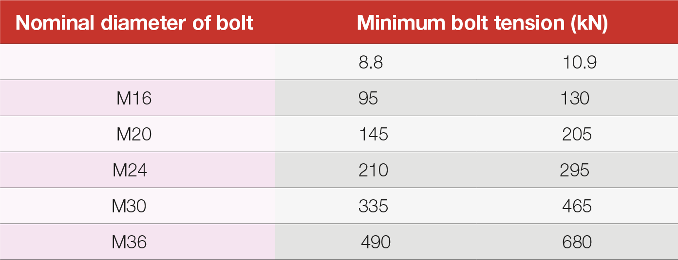
Table 19: Nut rotation from the snug tight position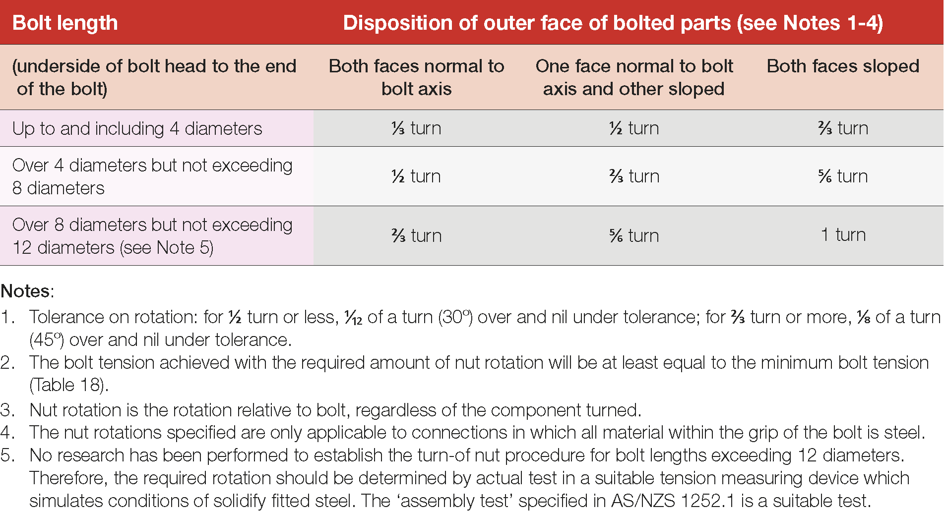
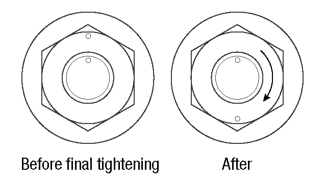
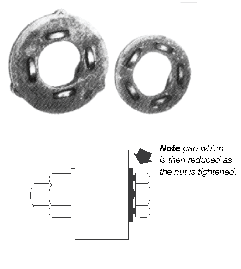
Table 18: Minimum bolt tension after tightening for high strength bolts
Table 19: Nut rotation from the snug tight position

