Search

Frames and fabrications

Design details are important when fabricated articles are to be hot dip galvanized.

Figure 14 to Figure 24 show basic design practices to ensure articles are able to be successfully galvanized and a quality hot dip galvanized coating is achieved. 

Some designs can provide adequate natural drainage without requiring holes (Figure 24).

Using Hollow Sections

External holes

  • External holes are needed to ensure quick visual inspection and verification that work is safe to galvanize.
  • Each member should have two holes in each end orientated in the plane of the fabrication.
  • External holes are to be placed as close to the connection as possible.
  • External holes size determined by 25% of the cross section. See ‘Standard Hole Size Tables’.  

Internal holes

  • Internal vent holes must be at least 50% of the connecting section. It is recommended they be the same size as the internal diameter of the connecting section where practical. See Figures 14 and 18.
  • Internal venting must be shown on shop detail drawings and be approved by the galvanizer prior to fabrication. This method of venting is also recommended to be approved by the structural engineer.
  • Internal holes must be visible or be able to be otherwise proven to be satisfactorily formed for inspection purposes.
  • A Ø10mm external check hole must be included at each location where internal venting is specified on the shop detail drawings. This best practice requirement will allow the galvanizer to safely proceed with dipping the article.

See ‘Location of holes’ and ‘Size of holes’ for more information.

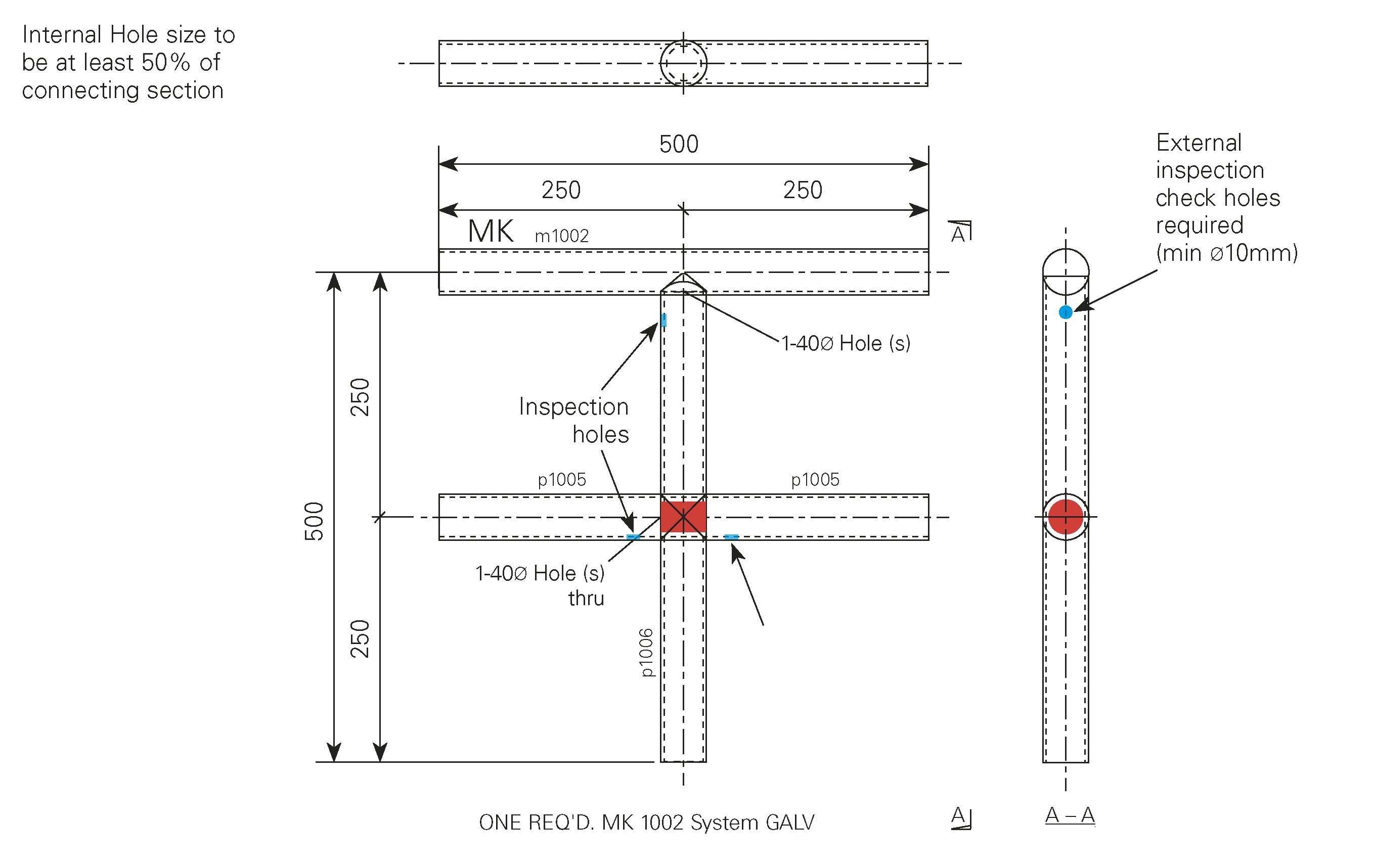
Hollow section end/base plate venting

Base plates and end plates welded to hollow sections require venting to allow pre-treatment fluids, zinc and air to escape during the galvanizing process. This will ensure that a high quality and uniform coating fully develops over the steel surface and eliminates the possibility of air pockets, zinc traps and bare spots. 

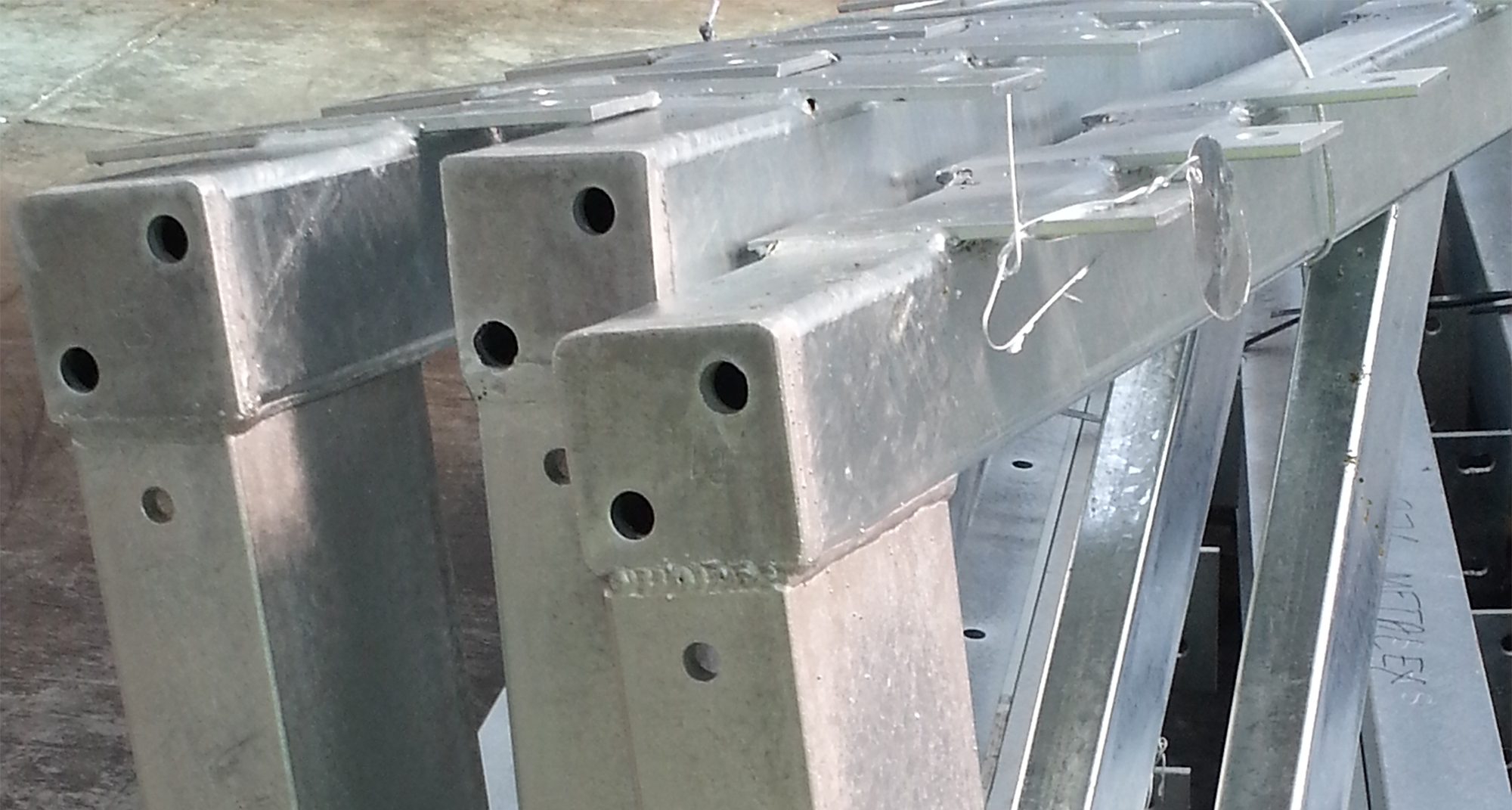
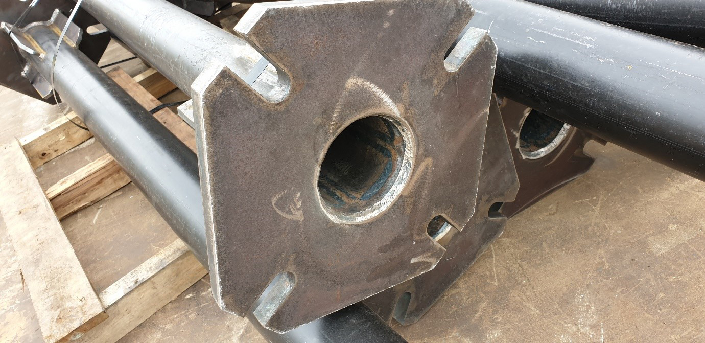
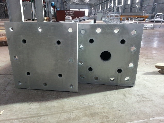
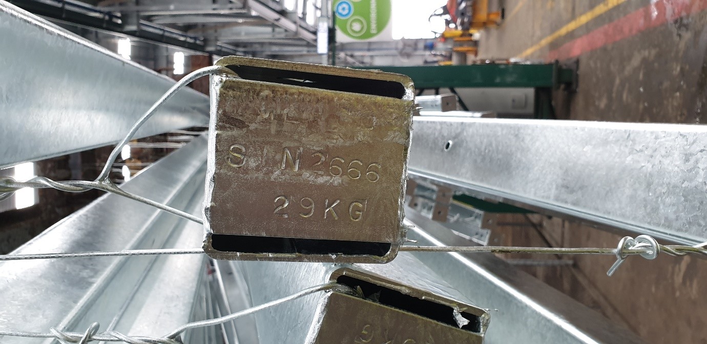
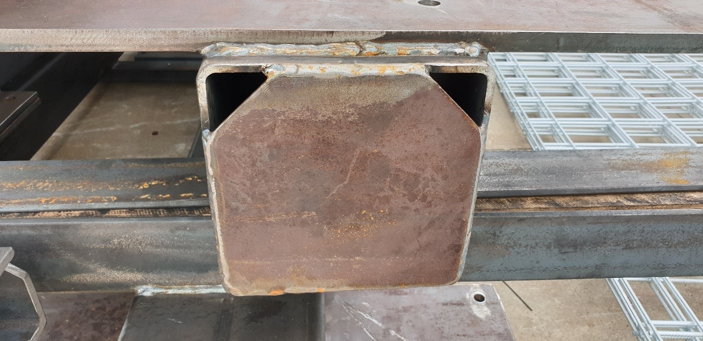
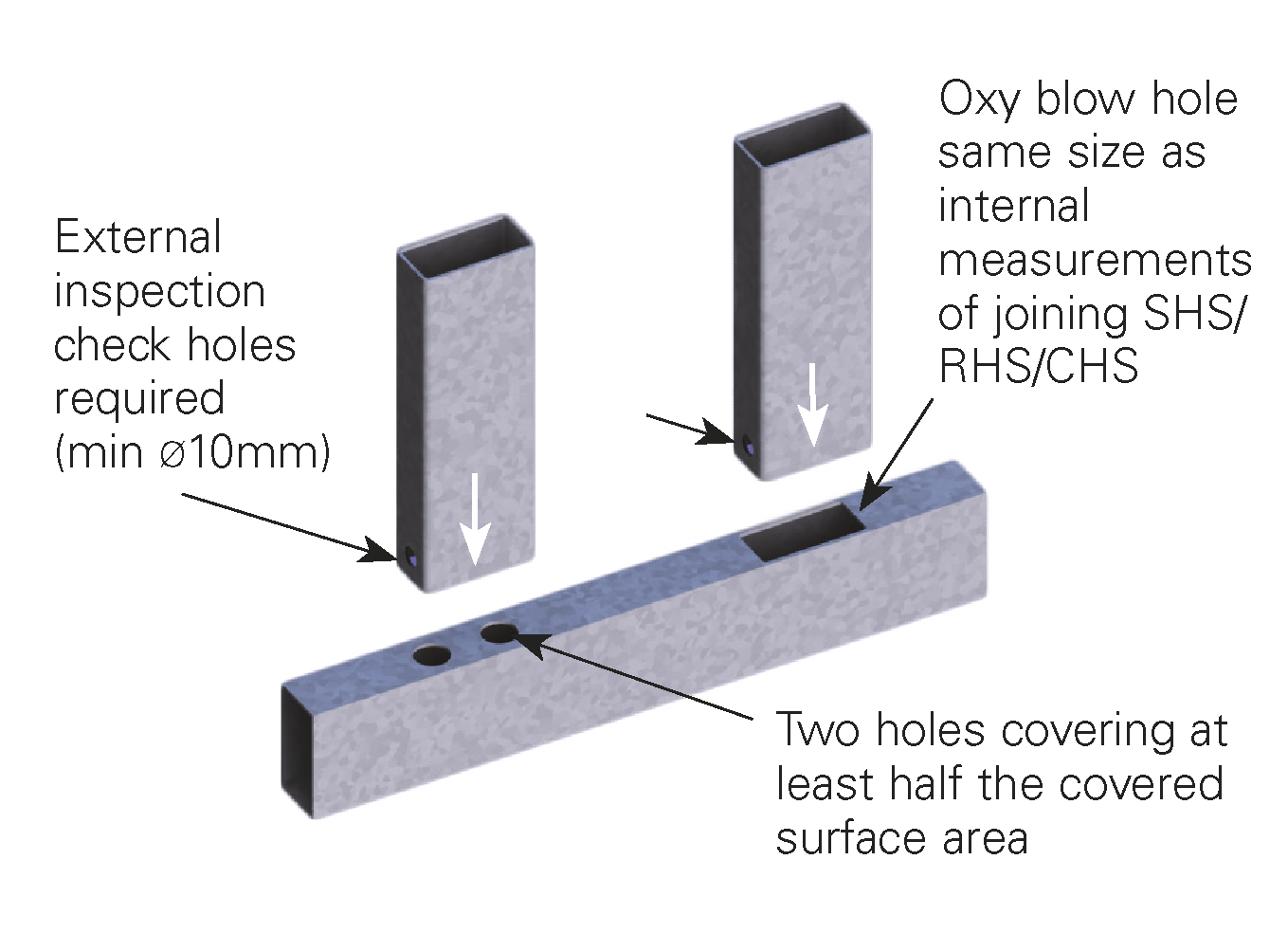
Hollow sections connected to a plate can be vented through the plate. It is preferential to have a completely vented area equal to the hollow section. 

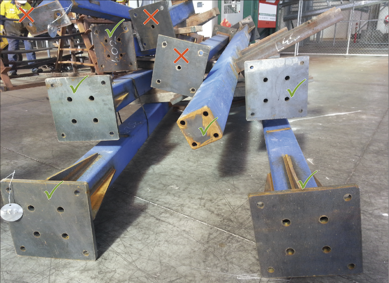
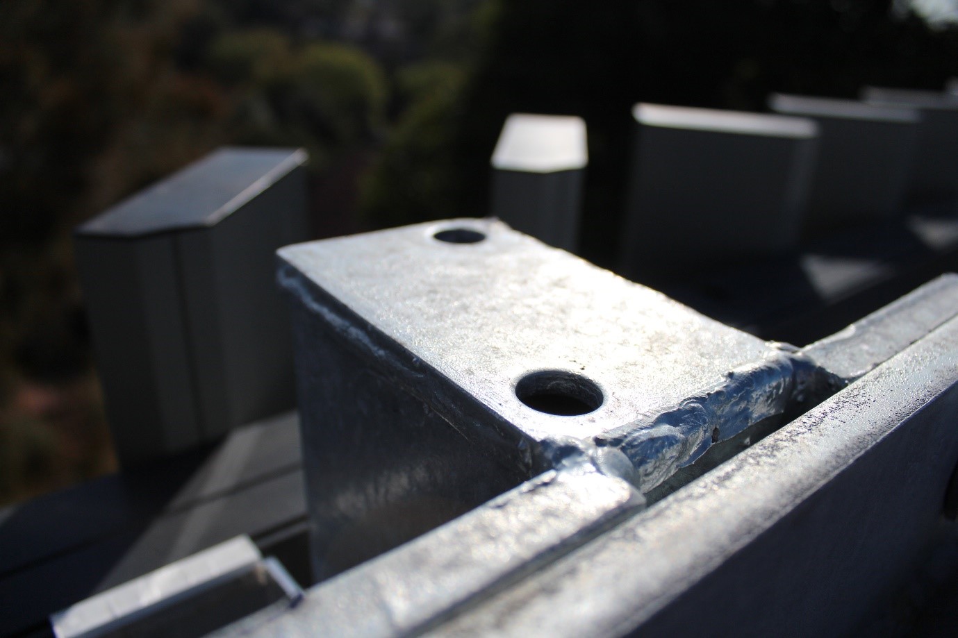
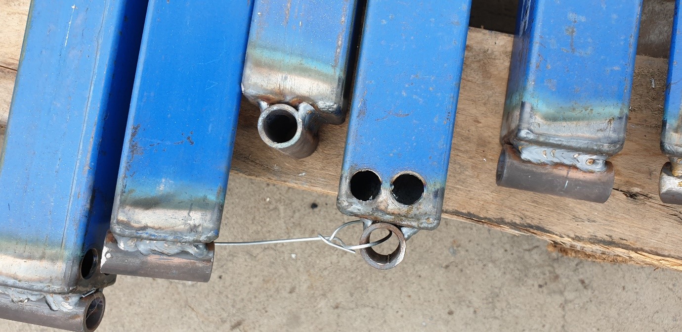
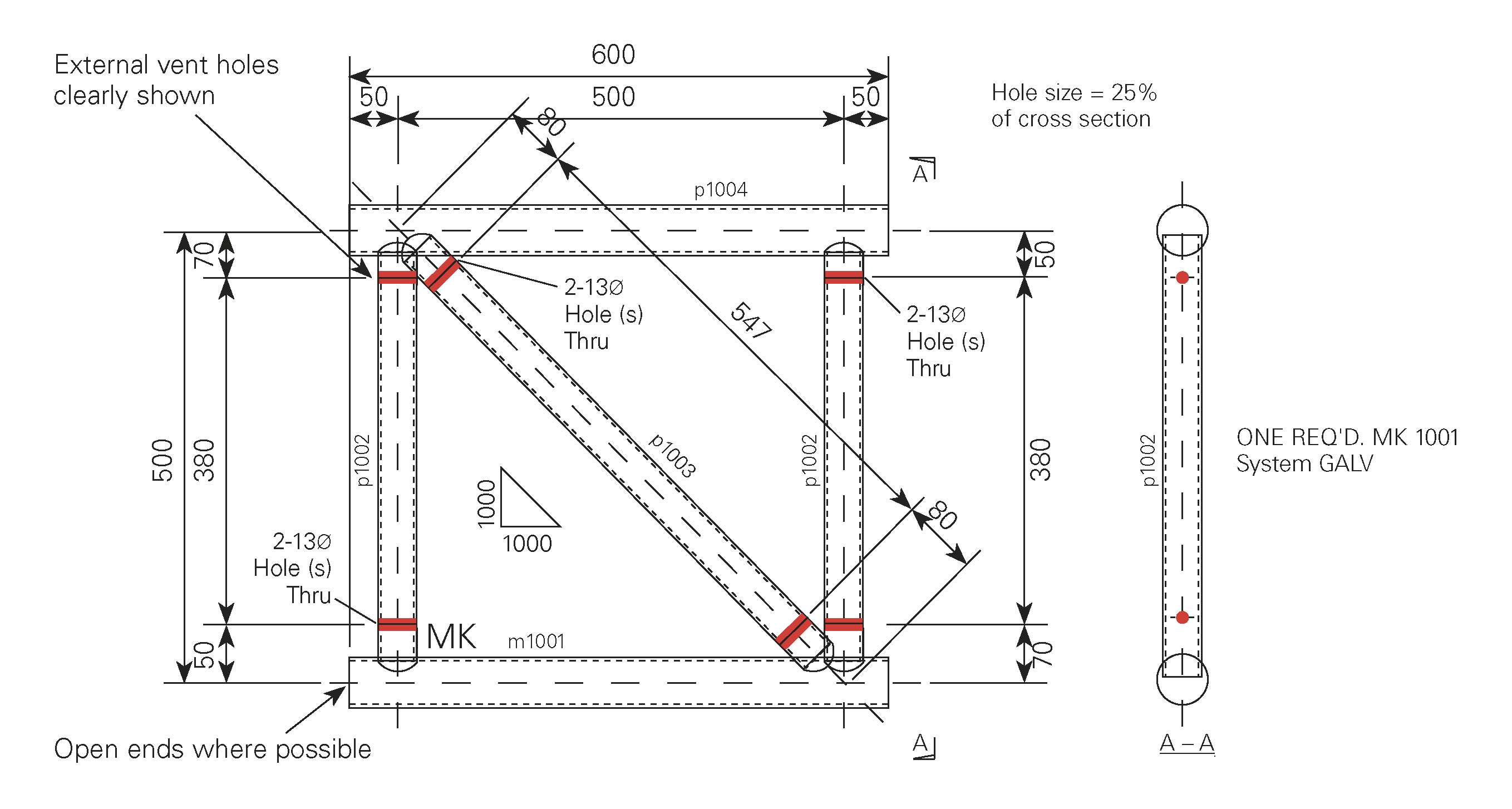
If it is not viable to remove the entire end of the hollow section for venting purposes, then smaller holes are acceptable. Provided they meet the requirements below. These holes should be located on the plate as close as possible to the corners of the hollow section.

A total of four holes, one in each corner is preferred. However a lesser number is acceptable provided the total area of these holes is equivalent to the minimum drainage requirements.

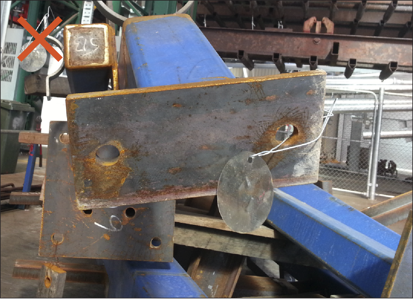
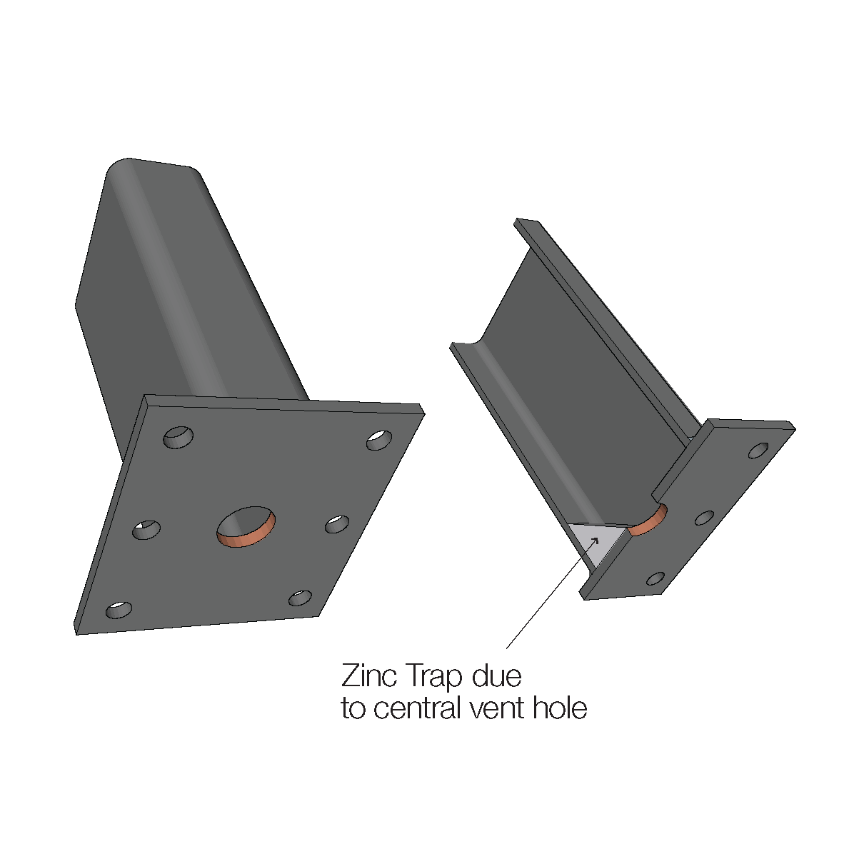
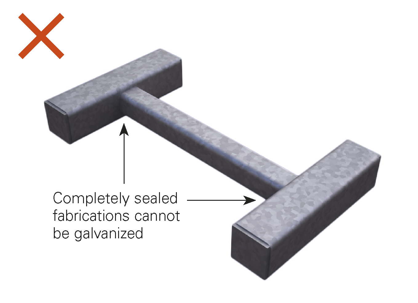
One central hole in the end plate is not acceptable as it does not allow for fluid drainage and can cause internal bare spots or zinc traps

Figure DN1. Completely vented end plates are best practice.
Figure DN3. Partially vented end plates in the form of cornered vent holes.
Figure DN5: Partial end plate venting.
Figure DN6. A centrally vented end plate will not allow the complete evacuation of fluids and will cause bare spots or zinc traps.
Figure 8. For safety reasons, Galvanizers will not accept centrally vented holes and may oxy-blow adequate vent holes which may not meet the required aesthetic appearance.
Figure DN10. Slotted end plate venting.
Figure DN11. Notched end plate venting.
Figure DN12. Cropped end plate.
Figure DN13. Externally vented end plate.

Using Other Structural Sections

Basic guidance on design, venting and draining for fabricated frames or articles using structural sections are given in Figures 20 through 24.

The same design principles related to ‘Hot Rolled Sections’ should also be applied to the use of these sections in frames and general fabrications.

Figure 14 – Closed Hollow Sections – Unsatisfactory

Figure 15 – Mitred Joints – Preferred

Figure 16 – External Venting Shop Detail – Preferred

Figure 17 – Internal Vent Holes with No Inspection Holes – Non-Preferred

Figure 18 – Internal Vent Holes – Drawing to clearly show items are “Internally Vented” with Inspection Holes – Preferred

Figure 19 – Internal Venting Shop Detail

Figure 20 – Venting Hot Rolled Frames

Figure 21 – Angle Connections Options

Figure 22 – Vented Frame

Figure 23 – Inward Facing Angles – Venting Required

Figure 24: Outward Facing Sections – Preferred

Hot rolled section end/base plate venting

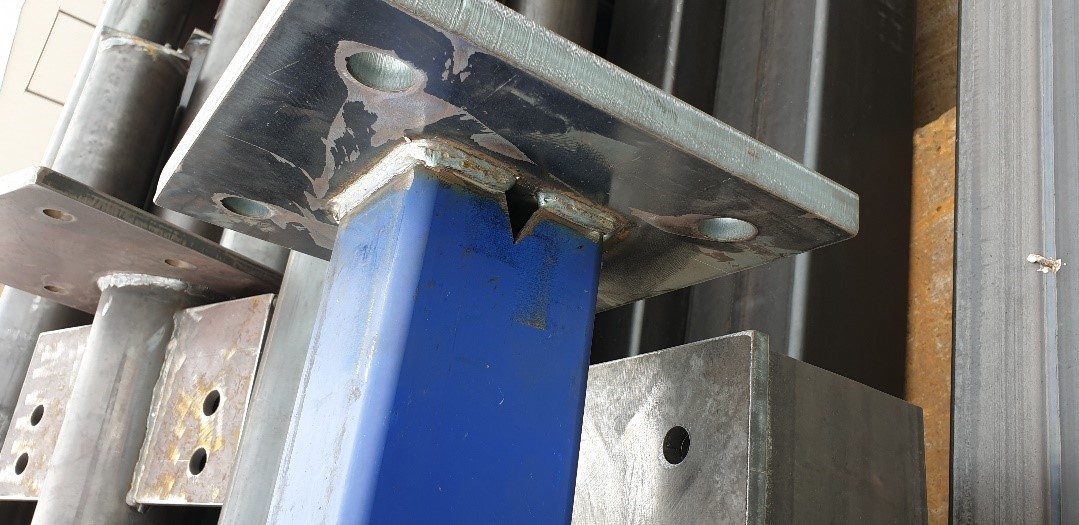
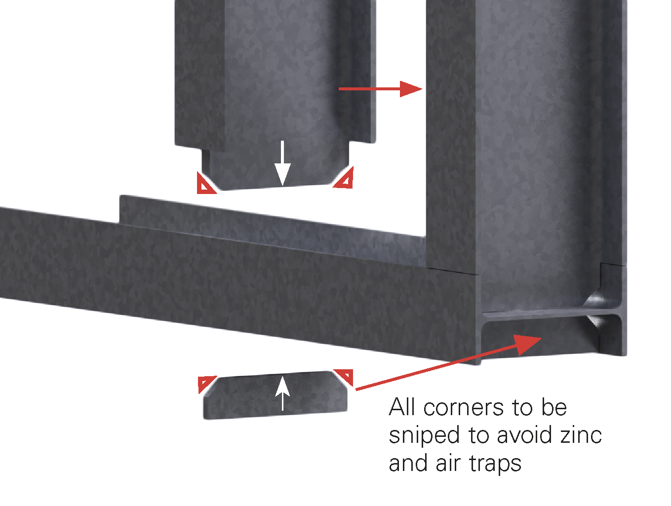
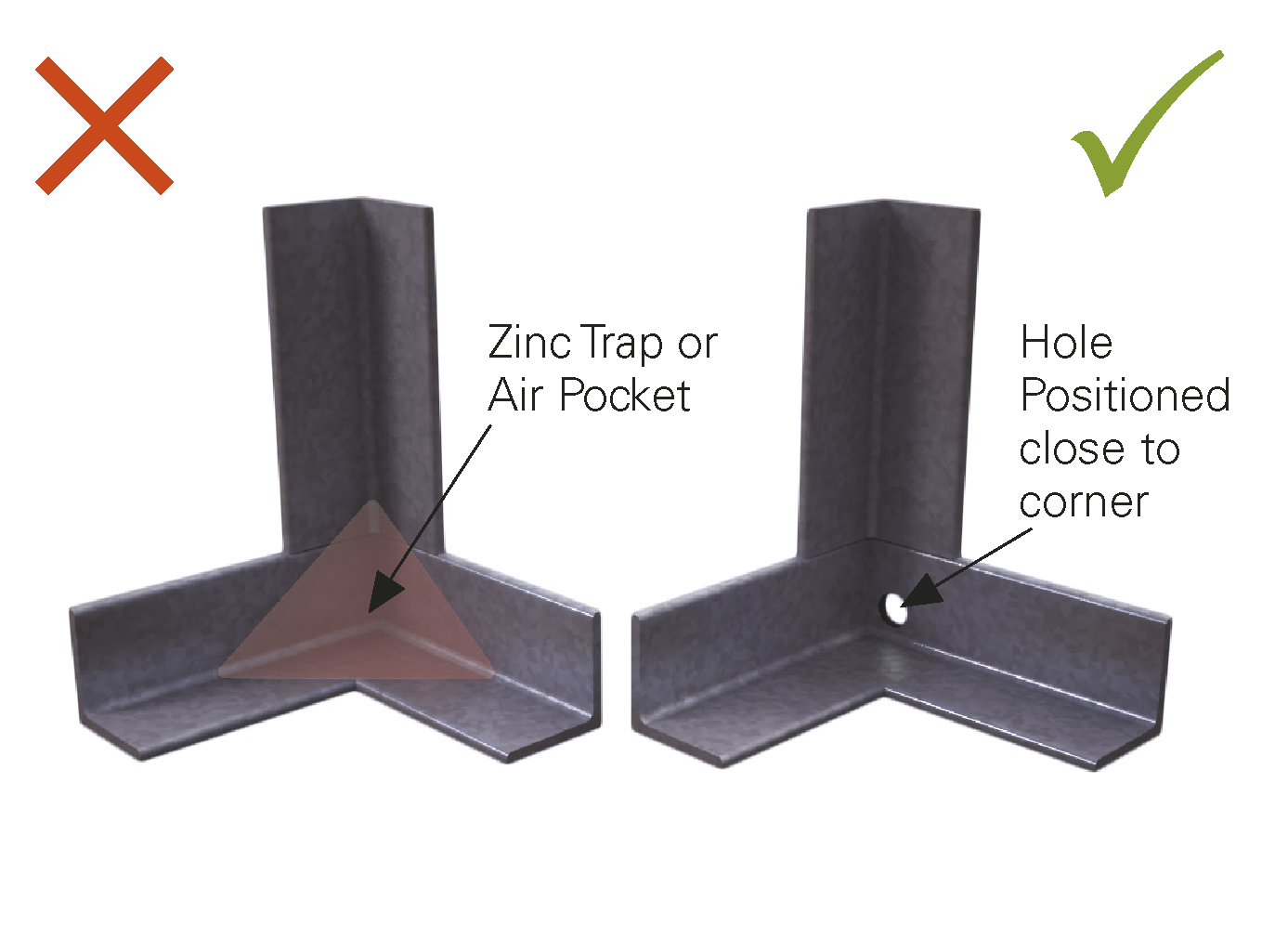
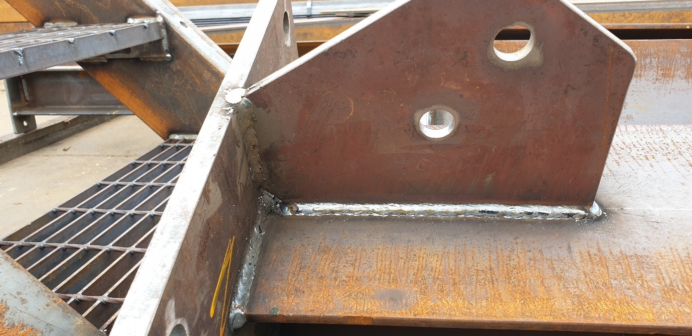
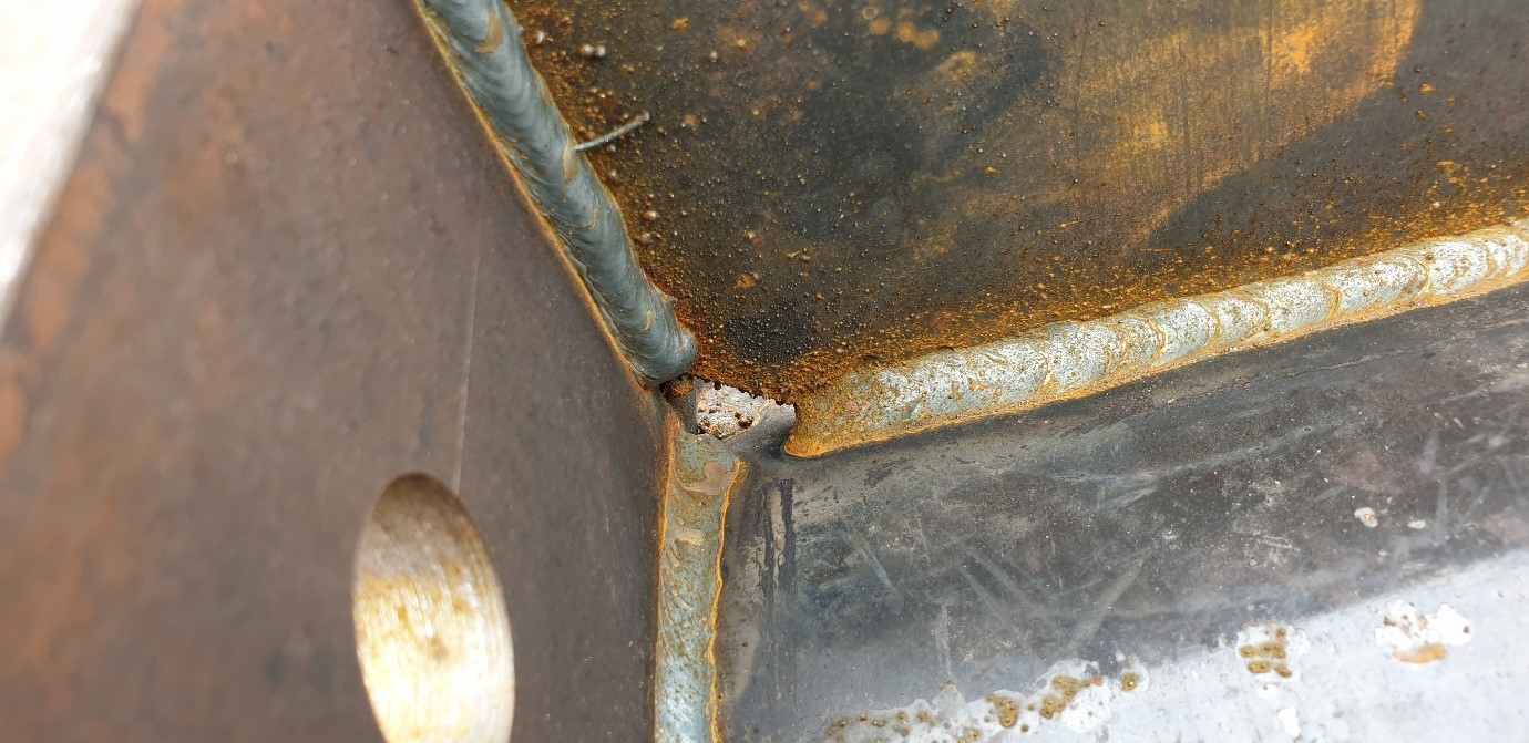
Base plates and end plates welded to hot rolled sections also require venting. Corners between section and plate can accumulate zinc, create an air trap or trap pre-treatment fluids. This can result in a lower quality surface finish or bare spots.

To avoid such issues, holes in the corners between the end plate and hot rolled section should be included in the fabrication. A hole in each corner is required to be at least 10 mm in diameter or larger, depending on the size of the section (Figures 14). Consult with your galvanizer for sizing requirements.

Figure DN14: Venting at the corners of end plate and hot rolled section is required to avoid zinc traps and air pockets.

Hot rolled section web notch venting

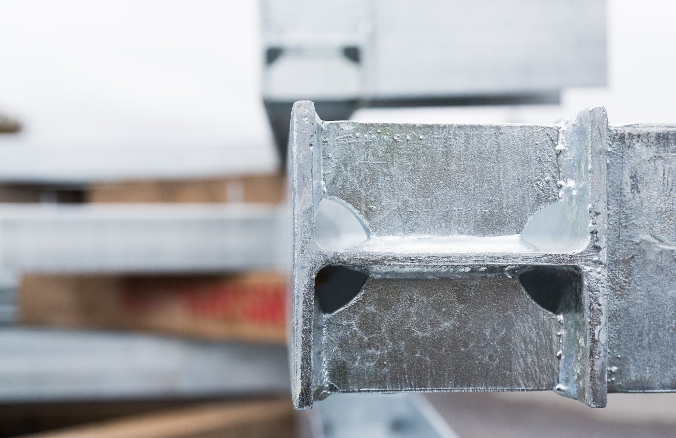
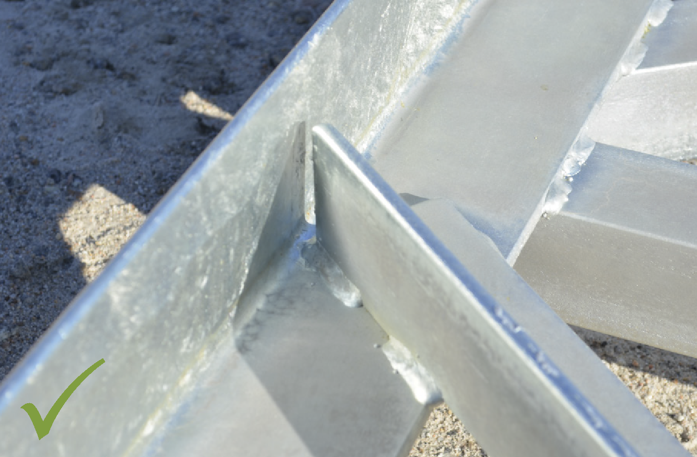
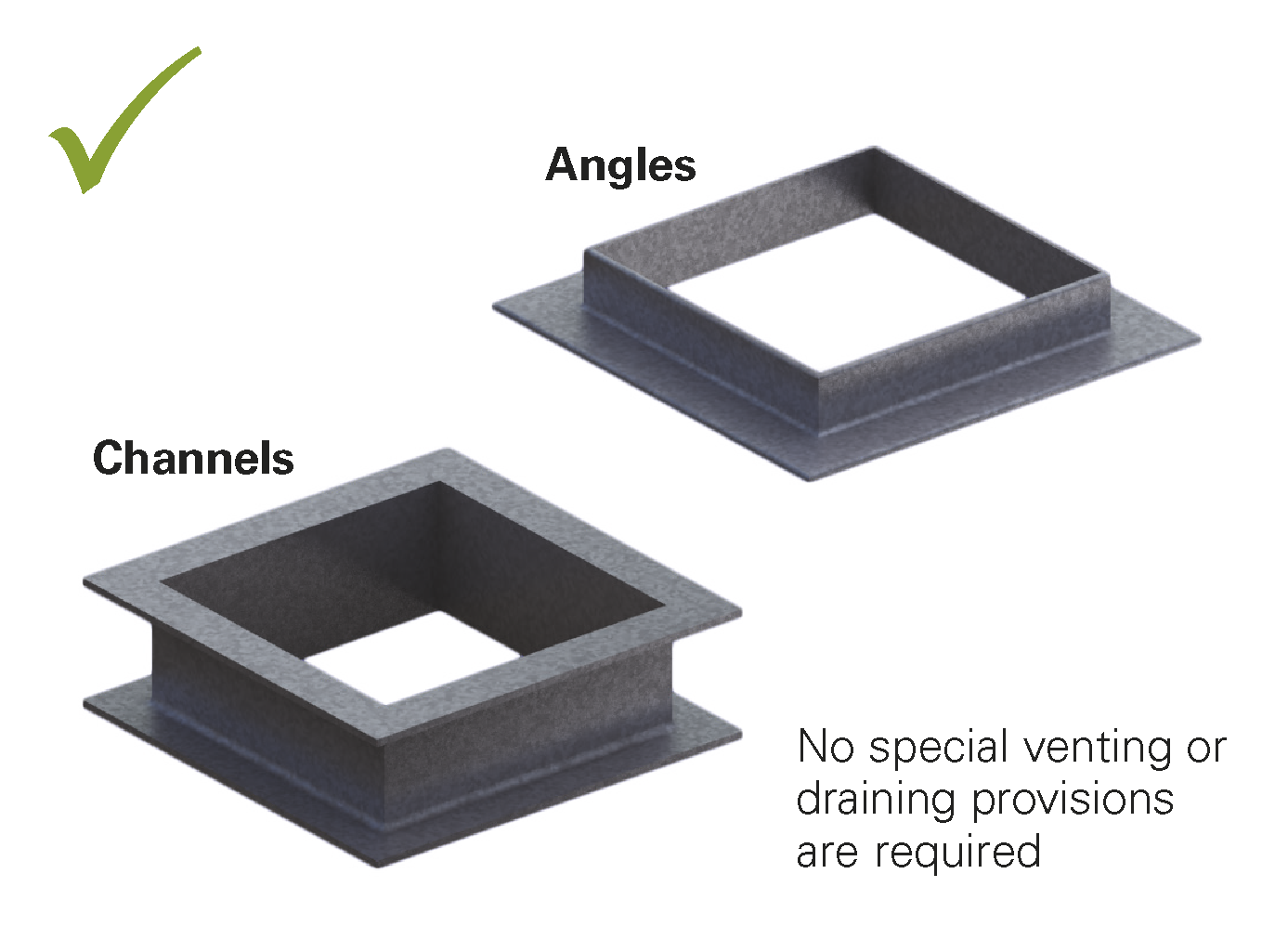
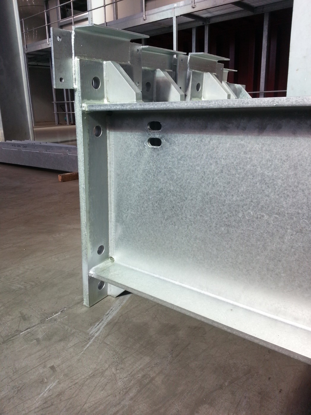
If design requirements do not allow for end plate venting, then venting in the form of notches in the hot rolled section web may prove adequate. These notches must be fabricated as close as possible to the corners between the end plate and flange. This will eliminate possible zinc traps and air pockets. Notches should be in the form of semi circles of at least 20 mm in diameter or in the form of snipes of at least 25 mm x 25 mm in size.


Figure DN16: Web snipe at the corner between end plate and hot rolled section.
Figure DN17: Circular web notches in the corners between end plate and hot rolled section.

Hot rolled section stiffener/channel/angle venting

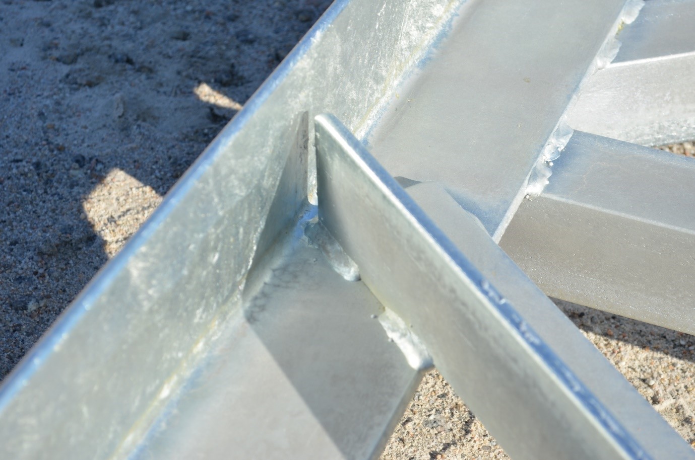
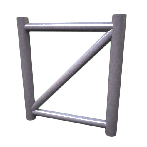
Stiffeners, cleats, flanges and gussets must all be designed into the fabrication such that
they do not inhibit the flow of pre-treatment fluids and zinc. Cleats and flanges should be welded with adequate gaps in the hot rolled section channel to avoid zinc traps and air pockets (Figure 19). Venting in the form of snipes on the corners of stiffeners and gussets will allow the free flow of zinc and air resulting in a high quality and uniform surface coating finish (Figures 20 & 21).

Snipes must be at least 25 x 25 mm in size and larger snipes may be required for larger sections. A table of required snipe sizes can be found for different sections in the “More information” segment of this design note.


Figure DN19: Gap have been considered in this design to allow the free flow of zinc.
Figure DN20: Cleats and stiffeners must be sniped at the corner.
Figure DN21: Channel stiffeners sniped at the corners to allow the free flow of zinc and air.