Search

Design for high strength bolting

AS 4100 specifies conditions for the application of high strength structural fasteners in both friction type and bearing type joints.

Bolts are tightened to the same minimum induced tension in both types of joint.

High strength fasteners in a friction-type joint (bolting category 8.8/TF or 10.9/TF) must be used where a bolted joint is designed and

  • slip in the serviceability limit state is to be avoided in a connection, or
  • the joint is subject to impact or vibration.

When non-slip fasteners (such as high-strength bolts in a friction-type connection or welds) are used in a connection in conjunction with slip-type fasteners (such as snug-tight bolts, or tensioned high strength bolts in bearing-type connections), all of the design actions must be assumed to be resisted by the non-slip fasteners.

Where bolts are designed to carry only tensile forces, the connection must be designed to carry any additional prying forces, which is the additional tensile force developed as a result of the flexing of a connection component in a connection subjected to tensile force.

All fasteners are required to have a washer under the rotated part to minimise damage to the surface and coating.

Bolt strength limit states

Bearing type joint design

Design capacity factors (Ø) for strength limit states of bolted connections

AS 4100 provides various capacity factors for bolted connections in bearing.

Table 9: Design capacity factors for bolted connectionsTable 9: Design capacity factors for bolted connections

Joints subject to shear and combined shear and tension

Design of a bearing type joint infers that some slip into bearing may take place. In bearing type joints, the design follows conventional practice based on allowable tension, shear and bearing values as specified in AS 4100.  Provided the joint surfaces are free from oil, dirt, loose scale, loose rust, burrs, or defects which would prevent solid seating, AS 4100 permits the use of hot dip galvanized coatings without a change in the design values.

Joints subject to shear force only

Bearing type joints subject to only shear force must be proportioned so that the shear force (Vf*) on any bolt does not exceed the nominal shear capacity of a bolt (Vf) multiplied by the capacity factor (Table 9).

Vf* ≤ øVf   

The nominal shear capacity is shown in Table 11 (for 4.6) and Table 12 (for 8.8) based on the following equation.

Vf = 0.62fufkrdkr (nnAc+ nxAo)

Where

fuf = minimum tensile strength of the bolt as specified in the relevant Standard (Table 8)

krd = Reduction factor to account for the reduced ductility of grade 10.9 bolts when subjected to shear where threads intercept the shear plane

= 1.0 for grade 4.6 and grade 8.8 bolts

= 1.0 for grade 10.9 bolts where threads do not intercept the shear plane

= 0.83 for grade 10.9 bolts where threads intercept the shear plane

kr = reduction factor (Table 10) to account for the length of a bolted lap connection (lj) and for all other connections kr equals 1.0

nn = number of shear planes with threads intercepting the shear plane

Ac = minor diameter area of the bolt as defined in AS 1275

nx = number of shear planes without threads intercepting the shear plane

Ao = nominal plain shank area of the bolt

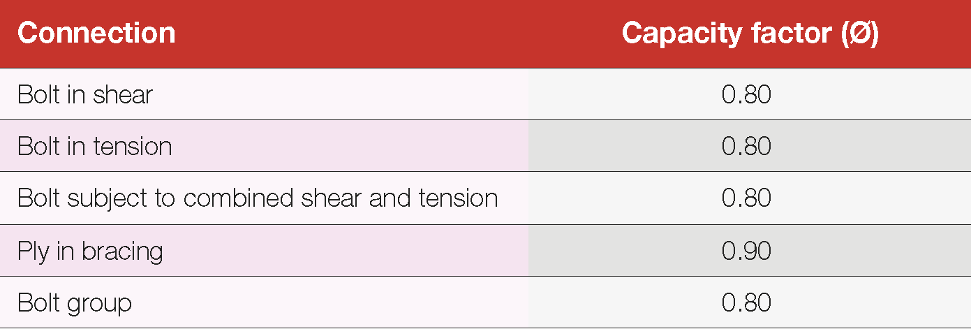
Table 10: Reduction factor for a bolted lap connection

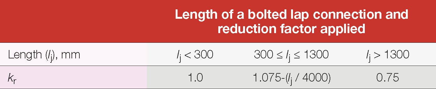
Table 11: Nominal shear capacities of commercial bolts – 4.6/S bolting category

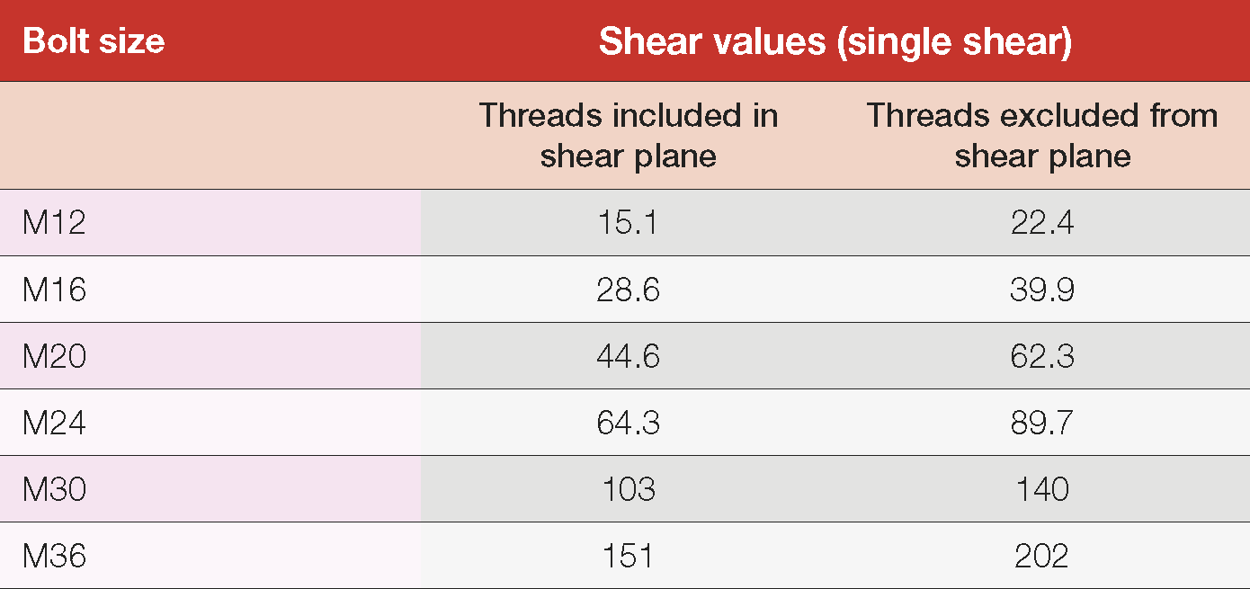
Table 12: Nominal shear capacities of high strength bolts – 8.8/S, 8.8/TB, 8.8/TF bolting categories

For property grade 10.9 bolts the following equations are used to calculate the shear values (Table 13). 

Vfn = 0.62F*ufAc

Vfx = 0.62F*ufAo

Where

F*uf – minimum tensile strength of a bolt (Table 8).

Ac – minor diameter of a bolt

Ao – nominal plane shank area of a bolt

Table 13: Nominal shear capacities of high strength bolts – 10.9/S, 10.9/TB, 10.9/TF bolting categories Table 13: Nominal shear capacities of high strength bolts – 10.9/S, 10.9/TB, 10.9/TF bolting categories

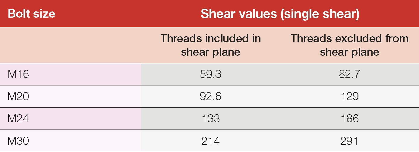
Joints subject to tension only

Tension type joints subject to only tensile force must be proportioned so that the tensile force (Nt*f) on any bolt does not exceed the nominal tension capacity of a bolt (Nf) multiplied by the capacity factor (Table 9). 

Nt*f ≤ øNtf 

Where:

Ntf = Asfuf

As = the tensile stress area of a bolt as specified in AS 1275

  Table 14: Nominal and design tension capacity on any bolt Table 14: Nominal and design tension capacity on any bolt

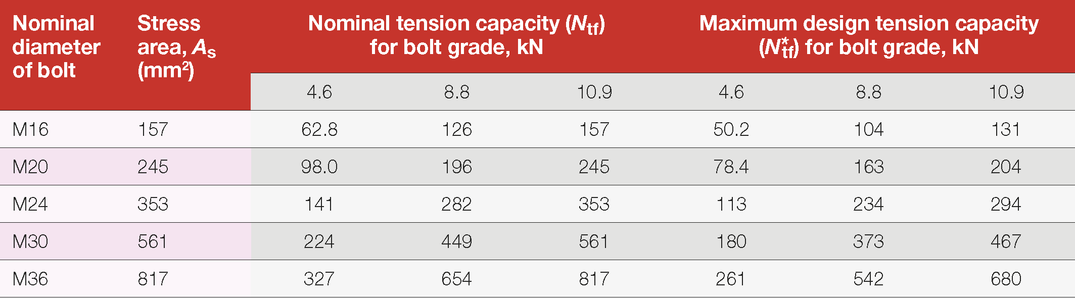
Joints subject to shear and tension

Bearing type joints subject to shear and tensile forces are to be proportioned so that the tensile force on any bolt does not exceed that permitted by the Parabolic Interaction Equation of AS 4100 (Clause 9.3.2.3).

Friction type joint design

Joints subject to shear force only

For friction-type connections (bolting categories 8.8/TF or 10.9/TF) in which slip in the serviceability limit state is required to be limited, a bolt subjected only to a design shear force (V*sf) in the plane of the interfaces must be equal to or lower than the nominal shear capacity of a bolt (Vsf) multiplied by the capacity factor Ø = 0.7.

V*sf ≤ ØVsf

Where

Vsf = μneiNtikh

 μ  = slip factor*

nei = number of effective interfaces.

Nti = minimum bolt tension at installation (provided in Table 15.2.2.2 of AS 4100).

kh = factor for different hole types, as specified in Clause 14.3.2 of AS 4100.

= 1.0 for standard holes.

= 0.85 for short slotted and oversize holes.

= 0.70 for long slotted holes.

*Slip factor is the coefficient of friction on the mating surfaces and can be defined as the ratio of the shear force between two plies required to produce slip to the force clamping the plies together. See Slip factors affecting mating surfaces for important aspects relating to slip factors on hot dip galvanized surfaces.

Maximum design shear capacities are shown in Table 15 for strength grade 8.8 bolts and Table 16 for strength grade 10.9 bolts.

Table 15: Design capacities of strength grade 8.8 bolts – Serviceability
limit state

Table 15: Design capacities of strength grade 8.8 bolts - Serviceability limit state

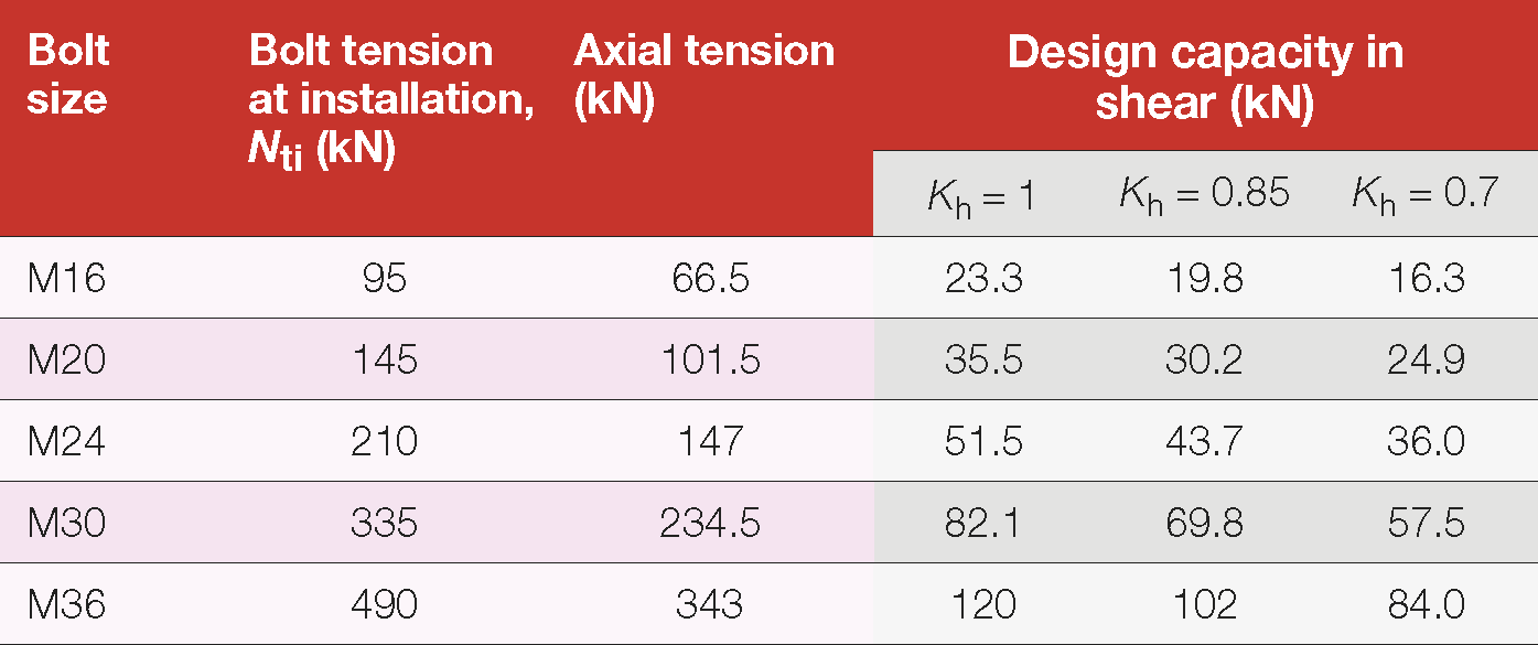
Table 16: Design capacities of strength grade 10.9 bolts – Serviceability
limit state

Table 16: Design capacities of strength grade 10.9 bolts - Serviceability limit state

Variation in design values with bolt strength and joint design

Design values vary with joint design, bolt type and level of bolt tightening. Table 17 shows the range of design values in shear which apply to bolts of the same nominal diameter (M20) in varying strength grades, used in various joint designs, in standard size holes (Kh =1), in accordance with AS 4100 (assumes slip factor = 0.35, where relevant).

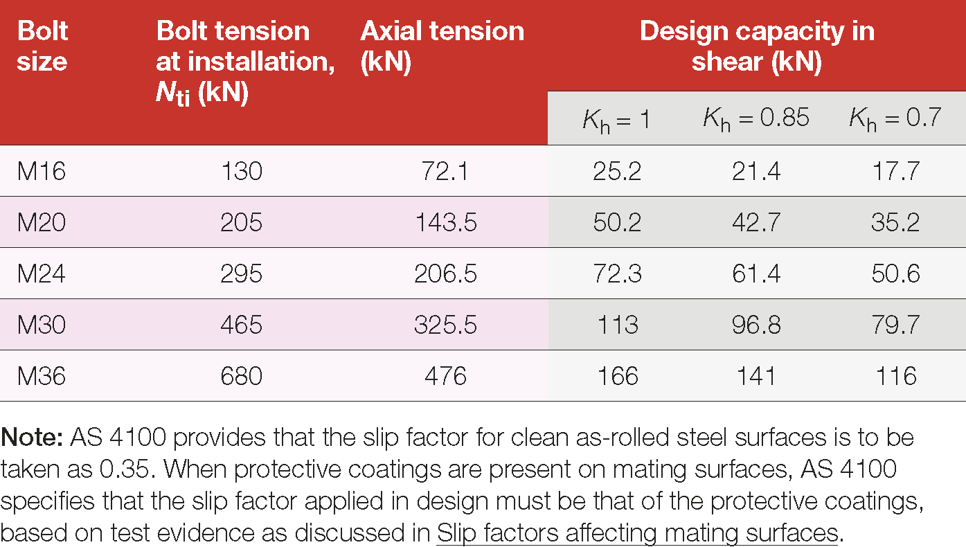
Table 17: Design values in shear of M20 bolts in various strength grades

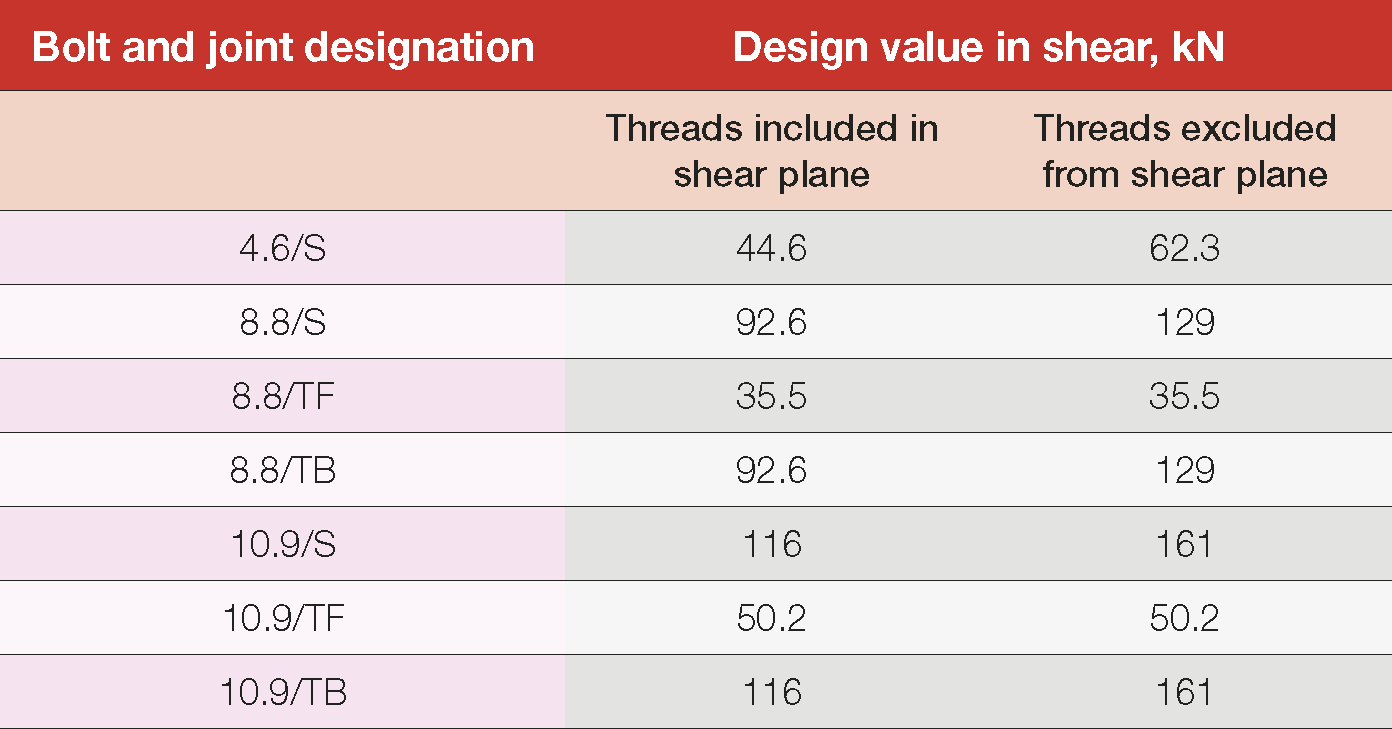
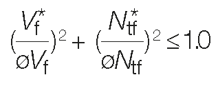
Joints subject to external tension in addition to shear

Bolts in a connection for which slip in the serviceability limit state is to be limited, which are subject to a design tension force (Nt*f ), must satisfy:
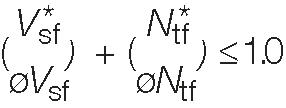
 Where:

V*sf = design shear force on the bolt in the plane of the interfaces.

Nt*f = design tensile force on the bolt.

 ø  = capacity factor (See Clause 3.5.5 of AS 4100).

Vsf = nominal shear capacity of the bolt as specified in Clause 9.3.3.1 of AS 4100.

Ntf = nominal tensile capacity of the bolt.

In this case, the nominal tensile capacity of the bolt (Ntf) is taken as:

Ntf = Nti

Where: 

Nti is the minimum bolt tension at installation as shown in Table 15 and Table 16.

The strength limit state must also be separately assessed in accordance with Clause 9.3.2.3 of AS 4100.

All fasteners are required to have a washer under the rotated part to minimise damage to the surface and coating.

Design values vary with joint design, bolt type and level of bolt tightening.

Figure 17: Modular construction is enabled through bolted connections

Design details for bolts

Hot dip galvanized structures that are to be joined using bolted connections should always have the bolt holes formed in the structural steel prior to galvanizing. This ensures full protection from corrosion in the bolt hole and maximises the life of the structure. In some designs, the inside of bolt hole may attract extra zinc from inadequate draining of the molten zinc. This can be left ‘as is’, or lightly cleaned if the bolt access is restricted. The area around a bolt hole should have any lumps or runs removed to ensure adequate flatness, although this is not generally a common problem. Care should be taken with any cleaning so as not to remove too much zinc and damage the protection. 

Centres

The minimum distance between the centres of fastener holes must be at least 2½ times the nominal diameter of the bolt (df).

The maximum distance between the centres of fastener holes must be the lesser of 200 mm or 15 x the thickness of the thinner connected ply. There are exceptions to this rule where corrosion of the steel can be avoided during the design lifetime (such as where a hot dip galvanized coating is used). In this case the maximum distance between centres can be increased to the lesser of 300 mm or 32 x the thickness of the thinner connected ply.

Edge distance

The minimum edge distance for a bolt hole from the edge of a section is related to the type of edge. For example, flame and machined cut edges require a larger edge distance than a hot rolled section edge.

  • Sheared or flame cut edge: 1.75 x df
  • Machine cut, sawn or planed edge: 1.50 x df
  • Rolled edge of a rolled flat bar or section: 1.25 x df

The maximum distance from the centre of any bolt hole to the nearest edge of parts in contact with one another is 12 x the thickness of the thinnest outer ply, but not exceeding 150 mm.

Hole Design

Normal bolt holes

The nominal diameter of a bolt hole (excluding bolt holes in base plates) is:

  • For dt ≤ 24 mm: 2 mm larger than df
  • For dt >24 mm: 3 mm larger than df

For base plates, the hole diameter is ≤ 6 mm larger than df. If the hole diameter is ≥ 3 mm more than df, a plate washer with a thickness ≥ 4 mm shall be used under the nut and the washer must be sized so that the distance from the edge of the hole to the edge of the washer is at least half the hole diameter.

Oversized bolt holes

Oversized holes are sometimes required for fabrication and erection purposes.

Oversized holes must have hardened washers or plate washers installed under both the bolt head and nut. The washer must be sized so that the distance from the edge of the hole to the edge of the washer is at least half the hole diameter.

Oversized holes must not be larger than the largest of 1.25 x df or df + 8 mm.

Slotted bolt holes

Slotted holes are described as either short or long slotted holes and, like oversize holes, are sometimes required for fabrication and erection purposes. Slotted holes should not be made except when noted on the specification.

Short slotted holes can be used on both friction-type and bearing-type connections (and in all or any of the plies). This type of bolt hole has certain restrictions in use for bearing-type connections subject to shear force. In this case they can only be used when the connection is not eccentrically loaded and the bolt can bear uniformly, and where the slot is normal to the direction of the design action.

Short slotted holes must have hardened washers or plate washers installed under both the bolt head and nut. The washer must be sized so that the distance from the edge of the hole to the edge of the washer is at least half the hole diameter.

The holes must not be wider than the allowances above for holes in general and must be no longer than the larger of 1.33 x df or df + 10 mm.

Long slotted holes can be used on both friction-type and bearing-type connections although they have tighter restrictions for use than short slotted holes and can only be used in alternate plies. In bearing-type connections subject to shear force they can only be used when the connection is not eccentrically loaded and the bolt can bear uniformly, and where the slot is normal to the direction of the design action.

A plate washer ≥ 8 mm thick must be installed under both the bolt head and nut and the washer must completely cover the hole and be sized so that the distance from the edge of the hole to the edge of the washer is at least half the hole diameter.


Hot dip galvanized structures that are to be joined using bolted connections should always have the bolt holes formed in the structural steel prior to galvanizing.